| Phone: +49(0) 5691-6287-0 | |||
| Fax: +49(0) 5691-6287-29 | |||
| Contact: mailto: JOERNS GmbH |
FINEPLACER®
Hot Air SMD Rework Stations
 |  |  |  | |
| FINEPLACER® core | FINEPLACER® coreplus | FINEPLACER® pico rs | FINEPLACER® micro rs | FINEPLACER® jumbo rs |
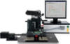
FINEPLACER® Camera
with auto fokus and auto zoom function
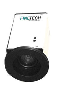
The auto-zoom camera is part of the vision alignment system (VAS) and is used instead of the microscope to position the components on printed circuit boards.
Zoom position and adjust the lighting can be saved for each component on a PCB, together with the reflow profile.
After loading their profiles, the camera automatically sets the optimum magnification and illumination intensity.
The image representation can be displayed on a separate monitor or using a frame grubber card on the PC monitor.
For the process protocol, images can be recorded and stored.
| Technical Specificationsp | |
| Field of view (max) | 75 x 56,3mm |
| Field of view (min) | 5 x 3,8mm |
| Resolution | 768 x 576pixel (PAL) 460 tv lines |
| Optical zoom | 25x |
| Digital zoom | 16x |
| light requirements (min) | 0,4lux |
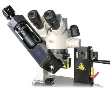
FINEPLACER® Process Video Module
The process video module allows observing the working area during the running process.
Camera and lighting systems, the high resolution camera can be pivoted 270 ° about the optical center line of the system.
These modules can be retrofitted for all FINEPLACER®.
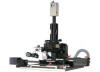
Process Video Modul RW2
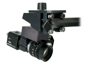
Rotatable around working area, fix inclination angle
Highlights*
- Live (in-situ) process observation
- Ideal for process optimization
- High magnification optics
- CCD video camera
- Ultrabright LED illumination
- Circular movement around the working area
- Different inclination angles available
* depending on configuration
| Technical Specifications | |
| Magnification (std.) | 47x @ 14" |
| Field of view (std.) | 4,5mm |
| Magnification (ext.) | 85x @14" |
| Field of view (ext.) | 2,5mm |
| Viewing angle (around working area) | 270° |
| Inclination angle | 10,6° |
| LED illumination | 3W |
| CCD video camera | 1/3" |
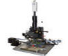
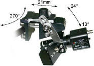
Process Video Modul RW3.X
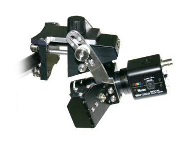
Rotatable around working area, variable inclination angle
Highlights*
- Live (in-situ) process observation
- Ideal for process optimization
- High magnification optics
- CCD video camera
- Ultrabright LED illumination
- Circular movement around the working area
- Different inclination angles available
* depending on configuration
| Technical Specifications | |
| Magnification (std.) | 34x @ 14" |
| Field of view (std.) | 6,2mm |
| Magnification (ext.) | 63x @ 14" |
| Field of view (ext.) | 3,4mm |
| Viewing angle (around working area) | 270° |
| Inclination angle | 13 - 23° |
| Movement along substrate surface | 21mm |
| LED illumination | 3W |
| CCD video camera | 1/3" |
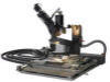
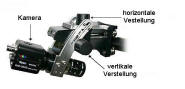
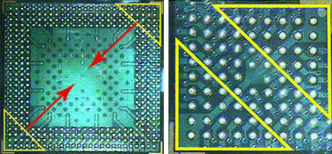
FINEPLACER® Split Field Optics
High accuracy requires high magnification resulting in small field of view. Thus, large components cannot be viewed entirely.
Split Field Optics allow two opposite corners of a large component and its corresponding pad area on the substrate to be viewed under high magnification.
This is achieved by "shifting" the image's corners in the direction of the optical center. Magnification as well as optical shift can be adjusted continuously.
Axial displacement
Highlights*
- Perfect for align large components with ultra fine pitch
- Extension of field of view
- Enhances application range
- Durable design Easy to use
* depending on configuration


